Albuquerque Third District N Scale Santa Fe Layout
Track Plans
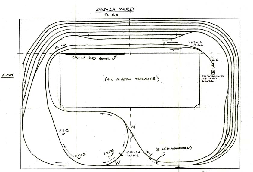
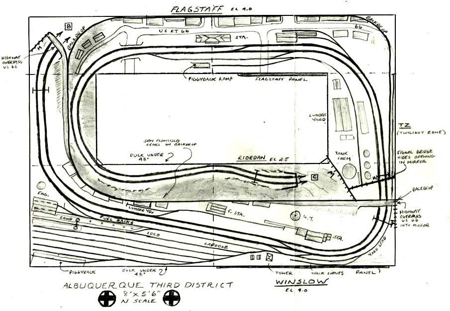
The layout is designed as a semi-modular plan built on six table sections to fit in a small spare bedroom. Overall size is 8 feet by 5 feet six inches. The lowest elevation (0") consists of a large, level storage yard capable of holding 4 25-car freight trains, 1 12 car passenger train, and 3 10-car local trains. All trains enter downhill through the N leg, to the E leg, and enter storage tracks turned and ready to exit. "Chi-La Yard" represents Chicago and Los Angeles, the east and west ends of the Santa Fe. Departing trains exit up the 2.5% grade to Williams Jct. on the second level.
These are the original pencil track plans developed in 1980-1, and are still in operation today with relatively minor changes to some sidings, and the 'abandonment' of the Chi-La wye back to a simple reverse loop.
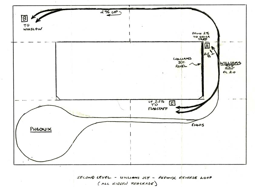
The second level consists of a reversing loop 2 inches above the storage yard, and the Williams Jct. area. This junction controls the reversing loop, entrance to Chi-La Yard, and the switches for both main line tracks. The combination of loops allows any train to be turned either entering or exiting the visible trackage so that all stored trains can be dispatched either eastbound or westbound to simulate heavy operations. The track at the top runs to the visible track to East Winslow and exits at the highway overpass, the other main exits to visible trackage out of the tunnel on Riordan hill. The Williams Jct. track switches are protected with a CTC-style interlocking signal system that only gives a green signal to one of four possible entrances with cleared switches.
The top, visible layer of the railroad simulates several specific scenes on the Santa Fe main line, designed around USGS topographical survey maps. Those include the Nelson Tunnel (though moved well east from its actual location), Riordan/Chalender with the distant view of the San Francisco Peaks, Flagstaff, Darling/Winona (then called "TZ"), Winslow Yard, and East Winslow.
Construction Photos and the Hidden Yards
Here's a few shots of the layout, under construction, in 1983. I only took a handful of shots that show what's hidden under the visible layout - the storage and reversing tracks. This approach was handy to get a layout up and running quickly - it took over a year to reach the upper visible layout level.
|
|
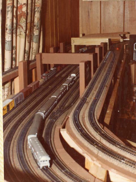
Chi-La yard, underneath Flagstaff - before Flagstaff was even built. The outer four storage tracks can each hold a 25-car train. The passenger train sits on a shorter track, and three smaller tracks hold local-size trains of 10 cars each. All trains enter the yard in the same direction, through a diode-matrix switch machine routing system. Trains automatically stop on isolated electrical sections that can only be restarted by holding down on momentary pushbuttons. This yard is virtually inaccessible, and although it has four inches of clearance, has proven to be difficult to maintain. Heavy trains and power keep the tracks clean, and 20 years of operation have proven that the construction has held. Track switches are on the front edge by the camera and easier to maintain than the tracks themselves. The two tracks on the right climb from the yard loop to Williams Jct. |
|
|
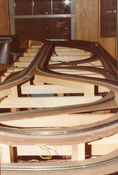
Phoenix reverse loop is two inches over the Chi-La yard level. This loop connects to Williams Jct., and is used to turn trains either leaving the yard, or returning the yard. This loop effectively governs the maximum train length of the layout at 25 cars plus power. The Riordan Hill main line was later built to the left side, and this entire area is now under the Winslow yard. A backdrop separates the scenes. Chi-La wye shows in the center of the shot. The "East" leg proved to be a design flaw, was unnecessary and difficult to operate, and eventually removed. The storage track now connects directly to the track just before the "West" leg. 2,5% grades in and out of this yard have proven to be practical for the maximum train length. |
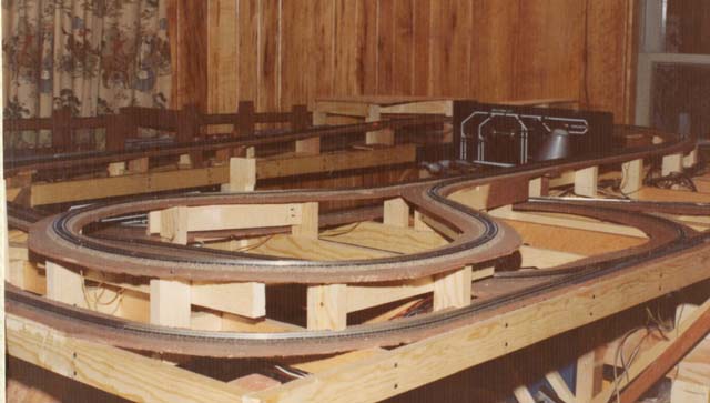 |
Another view of the layout with Chi-La yard in the background, the Phoenix Loop in the foreground, and the ramp connecting the two. Williams Jct. panel is in the background. This was the first of three locations for the layout, and it was moved only three months later. This table is the location of the 48" duckunder to the center operating pit. |